
This is a summary of my experience, and the exact steps I followed, to convert cheap Tuya based WiFi smart plugs to ESPHome for Home Assistant integration.
I am a novice when it comes to ESPHome, and I pieced information together from various great sources:
- Tuya Convert project.
- ESPHome Tuya Convert guide.
- ESPHome migrating from Tasmota guide.
- ESPHome Config device templates.
- Blakadder device templates.
- DigiblurDIY Tuya Convert guide.
- Frenc power plug calibration guide.
My goal was to use Tuya Convert, for it allows over the air firmware conversion, and no physical disassembly and firmware programmer wiring is required. Unfortunately I found that many currently shipping versions of plugs that apparently used to work no longer work, possibly contributed by Tuya switching from ESP82xx to Realtek chips. The model numbers and physical appearance of the plugs did not change, making it difficult to predict what you will get if you buy now.
As of September 2020, I tested the following plugs, all bought from Amazon:
| Model | Type | Result |
| Teckin SP10 | Relay | Fail |
| Teckin SP20 | Relay and Power Sensor | Fail |
| Aoycocr X5P | Relay | Success |
| Aoycocr X10S | Relay and Power Sensor | Fail |
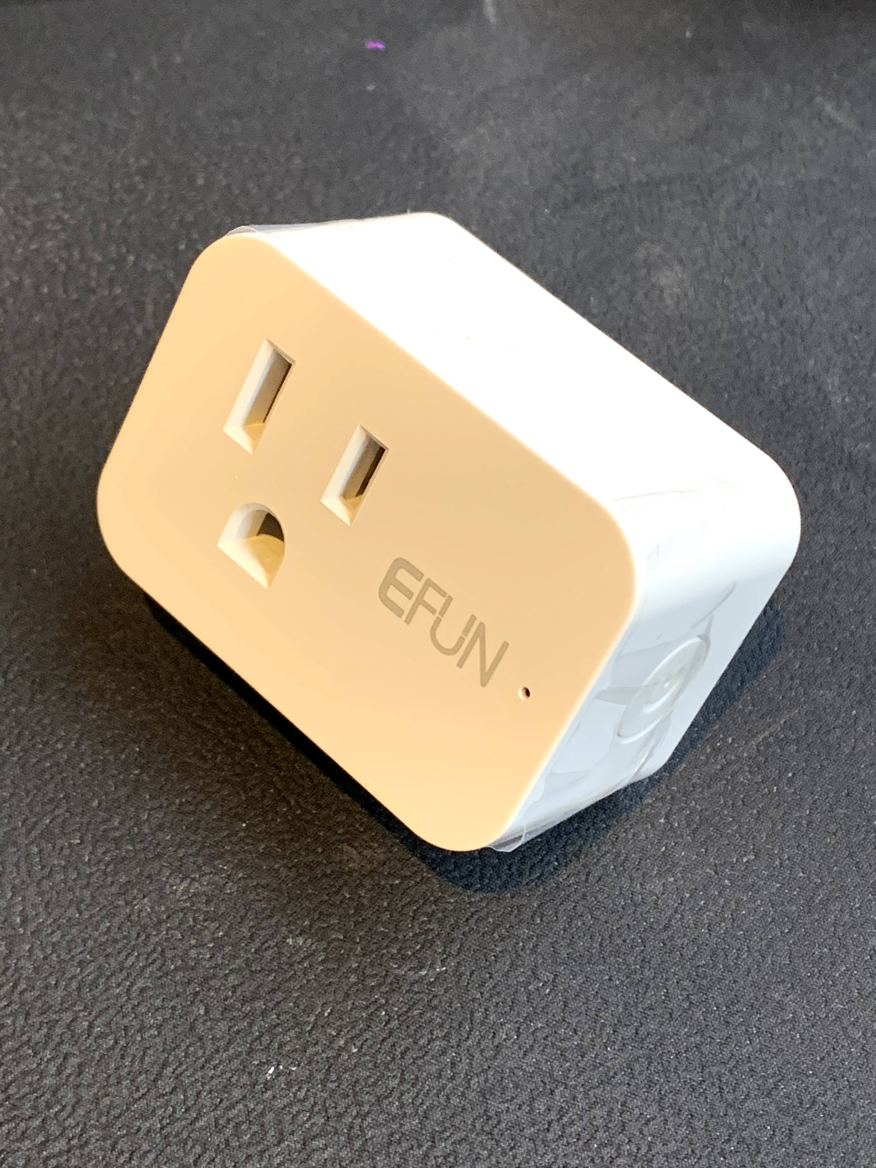
| EFUN SH331W | Relay and Power Sensor | Success |
| BN-LINK U133TJ | Relay and Power Sensor | Fail |


Here are the steps I took to convert the plugs from Tuya to Tasmota to ESPHome:
- Use Raspberry Pi Imager to install Raspberry Pi OS Lite on a microSD card. Other Linux platforms are supported, if the hardware has a compatible WiFi card, but I had a Raspberry Pi 4 B on hand.
- Create a
sshfile in the root folder of the SD card to enable SSH for headless remote access. - Boot the Raspberry Pi 4 using the created micro SD card, and make sure the Pi is connected using a LAN cable. WiFi will be used as an access point during conversion, and should not be used to connect to the Pi.
- SSH to the Pi using your favorite SSH client. On Windows 10 you can use the Windows Terminal app available from the Microsoft Store. E.g.
ssh pi@raspberrypi. The default username ispi, the default password israspberry, the default hostname israspberrypi. - Run
sudo raspi-config. Change the password, expand the available storage, set the WiFi country code, but do not connect to a WiFi network. - Update the Pi using
sudo apt update,sudo apt upgrade, then reboot usingsudo reboot, and reconnect over SSH. - Install Git using
sudo apt install git. - Clone Tuya Convert using
git clone https://github.com/ct-Open-Source/tuya-convert. - Install Tuya Convert dependencies using
cd ./tuya-convertandsudo ./install_prereq.sh. - Reboot using
sudo reboot, and reconnect using SSH. The multiple reboots may not be required, but I habitually reboot after making substantial system changes. - Start the conversion tool by
cd ./tuya-convertandsudo ./start_flash.sh. - Follow the on-screen instructions, confirm Yes when asked to terminate
dnsmasqandmosquitto, the network ports are required for the update process. - Connect your phone to the
vtrust-flashWiFi network created by Tuya Convert. I don’t know exactly why this step is required, and I don’t want to speculate. You could really use any device, or to simplify the steps, you could program an ESP device to automatically connect whenever the AP comes online. I made a 2-line modification to this ESP8266 code and programmed one of my ESP32 NodeMCU devices to automatically connect. - Power on the smart plug and put it in linking mode, e.g. 5s button press until the LED blinks fast. My Aoycocr plug immediately went into linking mode when powered on, and I did not have to press any buttons.
- After a few seconds the device will connect to the AP hosted by the Tuya Convert app, and you will be asked what firmware to use for programming. I used the default Tasmota firmware included with the package, and selected option 2 for
tasmota.bin. The plug rebooted after a successful firmware update. - Use your phone to connect to the
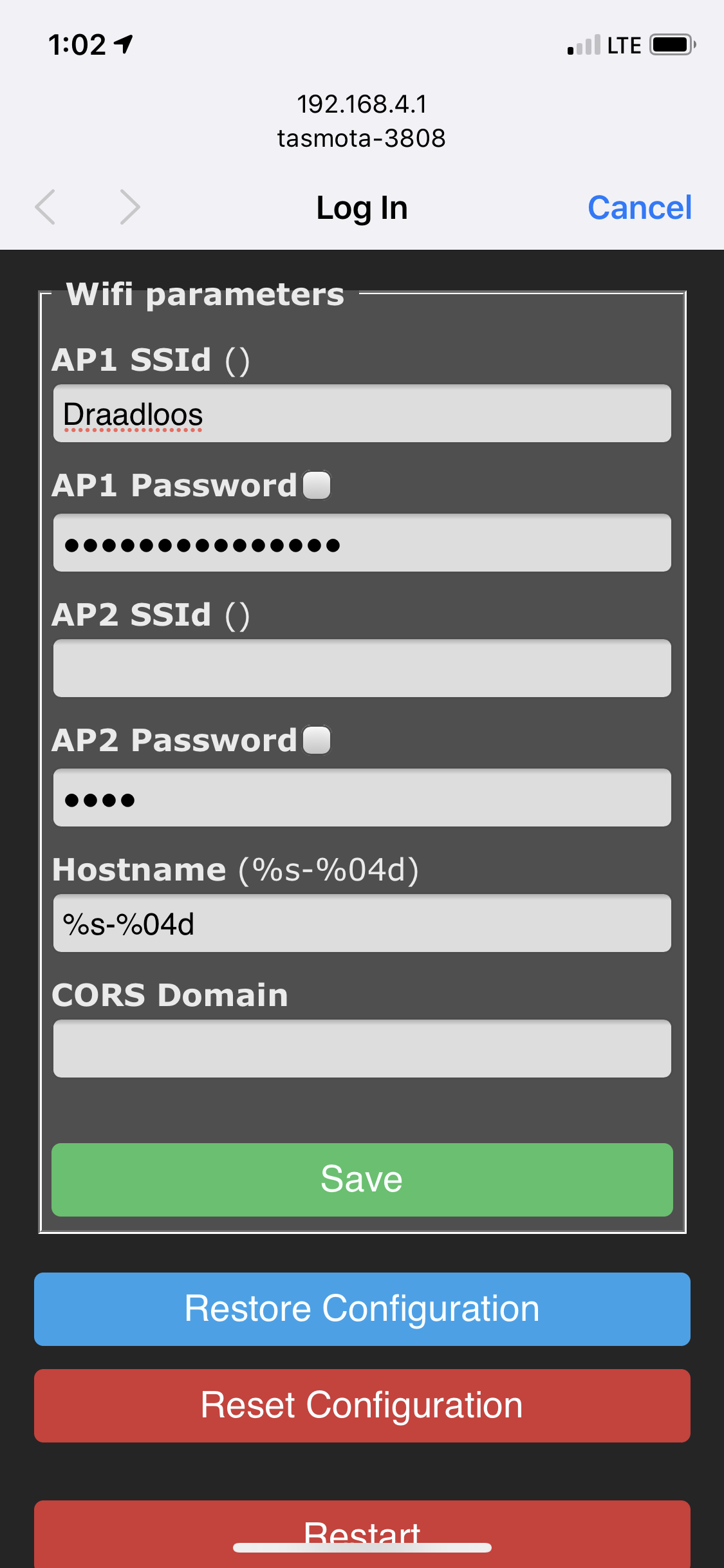
tasmota-xxxxWiFi network, your phone will display the captive portal page, and allow you to configure the plug to connect to your WiFi network. Make a note of the device name, same as the SSID, you can use this later instead of looking up the DHCP address. - After the device reboots, it will connect to your WiFi network using DHCP. Open the device web page in your browser by using the device name, e.g.
http://tasmota-xxxx/, or look at your router and the DHCP page to find the device IP address. My device showed it was running Tasmota v8.1.0.2. - Per the migration guide, a configuration change has to be made before flashing Tasmota v8.x to ESPHome v1.14.x firmware. Open the Tasmota console and enter
SetOption78 1, then return to the main menu to complete the firmware update. If you do not set this option, the ESPHome firmware update will fail. - Create a new ESPHome device in the ESPHome console, select Generic ESP8266 as device type, and enter the WiFi details. The detailed device configuration should be done later. Converting from Tasmota to ESPHome should be done with a minimal firmware configuration. Compile and download the firmware file to disk.
- Open the Tasmota web page, and upgrade the firmware using the ESPHome firmware file previously saved to disk.
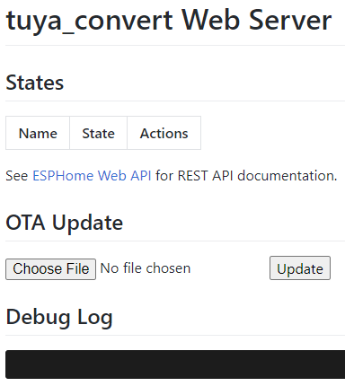
- On a successful upgrade the device will reboot, and web page will change from Tasmota to ESPHome, and the device will show up alive in the ESPHome console.
- When the device shows up alive in ESPHome, edit the configuration to match the specific device type.
- When converting multiple plugs, instead of creating multiple unique ESPHome firmware files for each device, you could create a generic device and convert all plugs with the same ESPHome firmware. Just be sure to keep only one device powered on at a time, and then rename the plug to a unique name follow the OTA renaming instructions.


I could not get the SP10, SP20, X10S, or U133TJ to convert. I did try this advice with the U133TJ, but it still failed.
Three out of four times Tuya Convert failed to download the EFUN SH331W backup firmware, download speed became very slow, and eventually timed out.
======================================================
Starting smart config pairing procedure
Waiting for the device to install the intermediate firmware
Put device in EZ config mode (blinking fast)
Sending SSID                  vtrust-flash
Sending wifiPassword
Sending token                 00000000
Sending secret                0101
................
SmartConfig complete.
Resending SmartConfig Packets
.............................
IoT-device is online with ip 10.42.42.42
Fetching firmware backup
  % Total    % Received % Xferd  Average Speed   Time    Time     Time  Current
                                 Dload  Upload   Total   Spent    Left  Speed
  0 1024k    0  5840    0     0     64      0  4:33:04  0:01:30  4:31:34     0
curl: Saved to filename 'firmware-398632.bin'
curl: (28) Operation timed out after 90001 milliseconds with 5840 out of 1048576 bytes received
Could not fetch a complete backup
Do you want to continue anyway? [y/N] y
But, in all cases the firmware was successfully converted.
======================================================
Getting Info from IoT-device
VTRUST-FLASH 1.5
(c) VTRUST GMBH https://www.vtrust.de/35c3/
READ FLASH: http://10.42.42.42/backup
ChipID: 398632
MAC: 80:7D:3A:39:86:32
BootVersion: 4
BootMode: normal
FlashMode: 1M DOUT @ 40MHz
FlashChipId: 144068
FlashChipRealSize: 1024K
Active Userspace: user2 0x81000
======================================================
Ready to flash third party firmware!

For your convenience, the following firmware images are already included in this repository:
  Tasmota v8.1.0.2 (wifiman)
  ESPurna 1.13.5 (base)

You can also provide your own image by placing it in the /files directory
Please ensure the firmware fits the device and includes the bootloader
MAXIMUM SIZE IS 512KB

Available options:
  0) return to stock
  1) flash espurna.bin
  2) flash tasmota.bin
  q) quit; do nothing
Please select 0-2: 2
Are you sure you want to flash tasmota.bin? This is the point of no return [y/N] y
Attempting to flash tasmota.bin, this may take a few seconds...
Flashed http://10.42.42.1/files/tasmota.bin successfully in 11672ms, rebooting...
Look for a tasmota-xxxx SSID to which you can connect and configure
Be sure to configure your device for proper function!

HAVE FUN!
The SH331W showed some instability, as I noticed it rebooting spontaneously on several occasions. There is a similar report for this plug running Tasmota. Per advice on the ESPHome Discord channel, I updated to ESPHome 1.15 Beta, and the problem seems to have been resolved.
The energy monitor chip used in these plugs are HLW8012 or equivalent BL0937, here is a good description of how they work. A key configuration parameter is the value of the current sense resistor, and the voltage divider network ratio. I looked at all the templates I could find, and many were using default values, or guessing values, or copying values from other plugs. Very few devices were disassembled and the actual component values measured.
| Device | Current Resistor | Voltage Divider |
| Default Value | 0.001 | 2351 |
| Kogan SmarterHome | 0.00087 | 2030 |
| AWP04L | 0.001 | 2401 |
| Sonoff POW R1 | Default | Default |
| Kogan SmarterHome | 0.00225 | 805 |
| Teckin SP-20 | 0.001 | 910 |
| Kogan SmarterHome | 0.0025 | 799 |
| Blitzwolf BW-SHP6 | 0.0029 | 940 |
| Blitzwolf BW-SHP7 | 0.002291 | 940 |
| Shelly Plug S | 0.0029 | 940 |
| Yeron US101 | 0.00087 | 2030 |
| Aoycocr-X10S | 0.001 | 2401 |
| BlitzWolf BW-SHP2 | 0.00221 | 955 |
| Brilliant Lighting BL20925 | Default | Default |
| NX-SP201 | 0.002452 | 814 |
| EFUN SH331 | 0.00221 | 940 |
Instead of disassembling and measuring the actual resistor values, I experimented to find a good starting point, using 1 mΩ for the current resistor and 940 for the voltage divider. I then calibrated the output using my ZHURUI PR10-E power meter. I used halogen bedside table lights and a hair dryer for load, they were the best I could do for loads with a power factor near 1.0.
Here are the results for one of the SH331 plugs:
| Load | Vm | V | Am | A | Wm | W | PF |
| Relay-Off | 119.2711 | 117.0000 | 0.0000 | 0.0110 | 0.0000 | 0.5900 | 0.4320 |
| Relay-On | 118.2908 | 117.0000 | 0.0097 | 0.0260 | 0.0000 | 1.5600 | 0.5100 |
| Halogen-1 | 115.1320 | 116.0000 | 0.9270 | 0.7570 | 198.5129 | 87.8300 | 0.9990 |
| Halogen-2 | 114.7508 | 115.9000 | 2.0133 | 1.6330 | 434.2469 | 189.5000 | 1.0000 |
| Hairdryer-3-1 | 114.4785 | 115.3000 | 2.9307 | 2.3750 | 628.6241 | 273.9000 | 0.9990 |
| Hairdryer-1-1 | 112.7357 | 113.9000 | 5.4848 | 4.4210 | 1067.0067 | 460.1000 | 0.9130 |
| Hairdryer-2-1 | 111.1019 | 112.2000 | 8.4308 | 6.8330 | 1619.8098 | 699.2000 | 0.9110 |
| Hairdryer-1-2 | 109.5769 | 110.7000 | 9.9171 | 7.9830 | 2043.0282 | 885.0000 | 1.0000 |
The “calibrated” results are much better than raw values, but still not accurate. The largest deviations are in reported power vs. V x A x PF values. I suspect that the results are non-linear when using “guessed” current sensing and voltage divider values.
Like I said, I’m no ESPHome expert, but maybe this helps somebody that is also getting started.
I created templates for the X5P and SH331 plugs, and then created instance YAML files for each plug instance. The upcoming ESPHome 1.15 introduces a native concept of packages, that should make it easier to avoid code duplication, e.g. note the large large code duplication between X5P and SH331 templates.
aoycocr_x5p_1.yaml:
substitutions:
  device_name: aoycocr_x5p_1
  device_comment: "Aoycocr X5P Smart Plug"

<<: !include templates/common.yaml
<<: !include templates/aoycocr_x5p.yaml
efun_sh331_1.yaml:
substitutions:
  device_name: efun_sh331_1
  device_comment: "EFUN SH331 Energy Monitoring Smart Plug"

<<: !include templates/common.yaml
<<: !include templates/efun_sh331.yaml
efun_sh331.yaml:
---
  # https://community.home-assistant.io/t/efun-sh331w-smart-plug-esphome-configuration-file/161112
  # https://templates.blakadder.com/efun_SH331W.html
  # https://www.belling.com.cn/media/file_object/bel_product/BL0937/datasheet/BL0937_V1.02_en.pdf

  # Button: GPIO13, Inverted
  # Relay: GPIO15
  # Red LED: GPIO0, Inverted
  # Blue LED: GPIO2, Inverted
  # BL0937 SEL: GPIO12, Inverted
  # BL0937 CF: GPIO5
  # BL0937 CF1: GPIO14

  # https://esphome.io/components/esphome.html
  esphome:
    name: ${device_name}
    comment: ${device_comment}
    platform: ESP8266
    board: esp01_1m
    # https://esphome.io/components/esphome.html#esp8266-restore-from-flash
    esp8266_restore_from_flash: true
    # https://esphome.io/components/esphome.html#on-boot
    on_boot:
      then:
        - if:
            condition:
              switch.is_on:
                id: relay
            then:
              - light.turn_on:
                  id: blue_led
                  brightness: 100%

  # https://esphome.io/components/binary_sensor/index.html
  binary_sensor:

    # https://esphome.io/components/binary_sensor/gpio.html
    - platform: gpio
      name: ${device_name}_button
      device_class: power
      pin:
        number: GPIO13
        inverted: true
      on_press:
        - switch.toggle: relay

    # https://esphome.io/components/binary_sensor/status.html
    - platform: status
      name: ${device_name}_status

  # https://esphome.io/components/text_sensor/index.html
  text_sensor:

    # https://esphome.io/components/text_sensor/version.html
    - platform: version
      name: ${device_name}_version

  # https://esphome.io/components/switch/index.html
  switch:

    # https://esphome.io/components/switch/gpio.html
    - platform: gpio
      name: ${device_name}_relay
      id: relay
      pin: GPIO15
      # Restore previous relay state on power-on
      restore_mode: RESTORE_DEFAULT_OFF
      on_turn_on:
        - light.turn_on:
            id: blue_led
            brightness: 100%
      on_turn_off:
        - light.turn_off: blue_led

  # https://esphome.io/components/output/index.html
  output:

    # https://esphome.io/components/output/esp8266_pwm.html
    - platform: esp8266_pwm
      id: red_output
      pin: GPIO0
      inverted: true

    - platform: esp8266_pwm
      id: blue_output
      pin: GPIO2
      inverted: true

# https://esphome.io/components/light/index.html
  light:

    # https://esphome.io/components/light/monochromatic.html
    - platform: monochromatic
      name: ${device_name}_red_led
      id: red_led
      output: red_output
      restore_mode: ALWAYS_OFF

    - platform: monochromatic
      name: ${device_name}_blue_led
      id: blue_led
      output: blue_output
      restore_mode: ALWAYS_OFF

  # https://esphome.io/guides/automations.html#interval
  interval:
    - interval: 500ms
      then:
        # https://esphome.io/guides/automations.html#if-action
        - if:
            condition:
              not:
                wifi.connected:
            then:
              - light.turn_on:
                  id: red_led
                  brightness: 100%
                  transition_length: 0s
              - delay: 250ms
              - light.turn_off:
                  id: red_led
                  transition_length: 250ms

  # https://esphome.io/components/sensor/index.html
  sensor:

    # https://esphome.io/components/sensor/wifi_signal.html
    - platform: wifi_signal
      name: ${device_name}_wifi_signal
      update_interval: 60s

    # https://esphome.io/components/sensor/uptime.html
    - platform: uptime
      name: ${device_name}_uptime
      unit_of_measurement: minutes
      filters:
        - lambda: return x / 60.0;

    # https://esphome.io/components/sensor/hlw8012.html
    - platform: hlw8012
      change_mode_every: 3
      update_interval: 3s
      sel_pin:
        number: GPIO12
        inverted: true
      cf_pin: GPIO5
      cf1_pin: GPIO14
      current_resistor: 0.001
      voltage_divider: 940
      current:
        name: ${device_name}_current
        unit_of_measurement: A
        filters:
          # https://esphome.io/components/sensor/index.html#calibrate-linear
          - calibrate_linear:
            - 0.0000 -> 0.0110 # Relay off no load
            - 0.0097 -> 0.0260 # Relay on no load
            - 0.9270 -> 0.7570
            - 2.0133 -> 1.6330
            - 2.9307 -> 2.3750
            - 5.4848 -> 4.4210
            - 8.4308 -> 6.8330
            - 9.9171 -> 7.9830
          # Normalize for plug load
          - lambda: if (x < 0.2600) return 0; else return (x - 0.0260);
      voltage:
        name: ${device_name}_voltage
        unit_of_measurement: V
        filters:
          - calibrate_linear:
            - 109.5769 -> 110.7000
            - 111.1019 -> 112.2000
            - 112.7357 -> 113.9000
            - 114.4785 -> 115.3000
            - 114.7508 -> 115.9000
            - 115.1320 -> 116.0000
            - 118.2908 -> 117.0000
            - 119.2711 -> 117.0000
      power:
        name: ${device_name}_power
        id: wattage
        unit_of_measurement: W
        filters:
          - calibrate_linear:
            - 0.0000 -> 0.5900 # Relay off no load
            - 0.0000 -> 1.5600 # Relay on no load
            - 198.5129 -> 87.8300
            - 434.2469 -> 189.5000
            - 628.6241 -> 273.9000
            - 1067.0067 -> 460.1000
            - 1619.8098 -> 699.2000
            - 2043.0282 -> 885.0000
          # Normalize for plug load
          - lambda: if (x < 1.5600) return 0; else return (x - 1.5600);

    # https://esphome.io/components/sensor/total_daily_energy.html
    - platform: total_daily_energy
      name: ${device_name}_total_daily_energy
      power_id: wattage
      filters:
        - multiply: 0.001
      unit_of_measurement: kWh
aoycocr_x5p.yaml:
---
  # https://templates.blakadder.com/aoycocr_X5P.html
  # https://esphome-configs.io/devices/aoycocr-x10s/

  # Button: GPIO13, Inverted
  # Relay: GPIO15
  # Red LED: GPIO0, Inverted
  # Blue LED: GPIO2, Inverted

  # https://esphome.io/components/esphome.html
  esphome:
    name: ${device_name}
    comment: ${device_comment}
    platform: ESP8266
    board: esp01_1m
    # https://esphome.io/components/esphome.html#esp8266-restore-from-flash
    esp8266_restore_from_flash: true
    # https://esphome.io/components/esphome.html#on-boot
    on_boot:
      then:
        - if:
            condition:
              switch.is_on:
                id: relay
            then:
              - light.turn_on:
                  id: blue_led
                  brightness: 100%

  # https://esphome.io/components/binary_sensor/index.html
  binary_sensor:

    # https://esphome.io/components/binary_sensor/gpio.html
    - platform: gpio
      name: ${device_name}_button
      device_class: power
      pin:
        number: GPIO13
        inverted: true
      on_press:
        - switch.toggle: relay

    # https://esphome.io/components/binary_sensor/status.html
    - platform: status
      name: ${device_name}_status

  # https://esphome.io/components/text_sensor/index.html
  text_sensor:

    # https://esphome.io/components/text_sensor/version.html
    - platform: version
      name: ${device_name}_version

  # https://esphome.io/components/switch/index.html
  switch:

    # https://esphome.io/components/switch/gpio.html
    - platform: gpio
      name: ${device_name}_relay
      id: relay
      pin: GPIO15
      # Restore previous relay state on power-on
      restore_mode: RESTORE_DEFAULT_OFF
      on_turn_on:
        - light.turn_on:
            id: blue_led
            brightness: 100%
      on_turn_off:
        - light.turn_off: blue_led

  # https://esphome.io/components/output/index.html
  output:

    # https://esphome.io/components/output/esp8266_pwm.html
    - platform: esp8266_pwm
      id: red_output
      pin: GPIO0
      inverted: true

    - platform: esp8266_pwm
      id: blue_output
      pin: GPIO2
      inverted: true

# https://esphome.io/components/light/index.html
  light:

    # https://esphome.io/components/light/monochromatic.html
    - platform: monochromatic
      name: ${device_name}_red_led
      id: red_led
      output: red_output
      restore_mode: ALWAYS_OFF

    - platform: monochromatic
      name: ${device_name}_blue_led
      id: blue_led
      output: blue_output
      restore_mode: ALWAYS_OFF

  # https://esphome.io/guides/automations.html#interval
  interval:
    - interval: 500ms
      then:
        # https://esphome.io/guides/automations.html#if-action
        - if:
            condition:
              not:
                wifi.connected:
            then:
              - light.turn_on:
                  id: red_led
                  brightness: 100%
                  transition_length: 0s
              - delay: 250ms
              - light.turn_off:
                  id: red_led
                  transition_length: 250ms

  # https://esphome.io/components/sensor/index.html
  sensor:

    # https://esphome.io/components/sensor/wifi_signal.html
    - platform: wifi_signal
      name: ${device_name}_wifi_signal
      update_interval: 60s

    # https://esphome.io/components/sensor/uptime.html
    - platform: uptime
      name: ${device_name}_uptime
      unit_of_measurement: minutes
      filters:
        - lambda: return x / 60.0;

Just flashed 4 of these thanks to your instructions. Thanks for the thorough write up!
LikeLike
Hi Pieter,
Just to say a big thank you for this comprehensive guide. Saved me a LOT of heartaches.
Best Regards,
Jean Carl Grech,
Malta.
LikeLike
Hello Pieter and thank you for the write-up! i am needing your help. this write-up covers tuya convert in great detail, ever command every procedure, but then when you get to the part of adding an ESPHOME config there is no instruction at all just to yaml files??? and they are massive with no working complete example code . can you please help a brother out and give the same quality info on configuration and set up of the plug in ESPhome as you did on the convention process. I have a plug with esp home on it but don’t know how to make those two files a working config
LikeLike