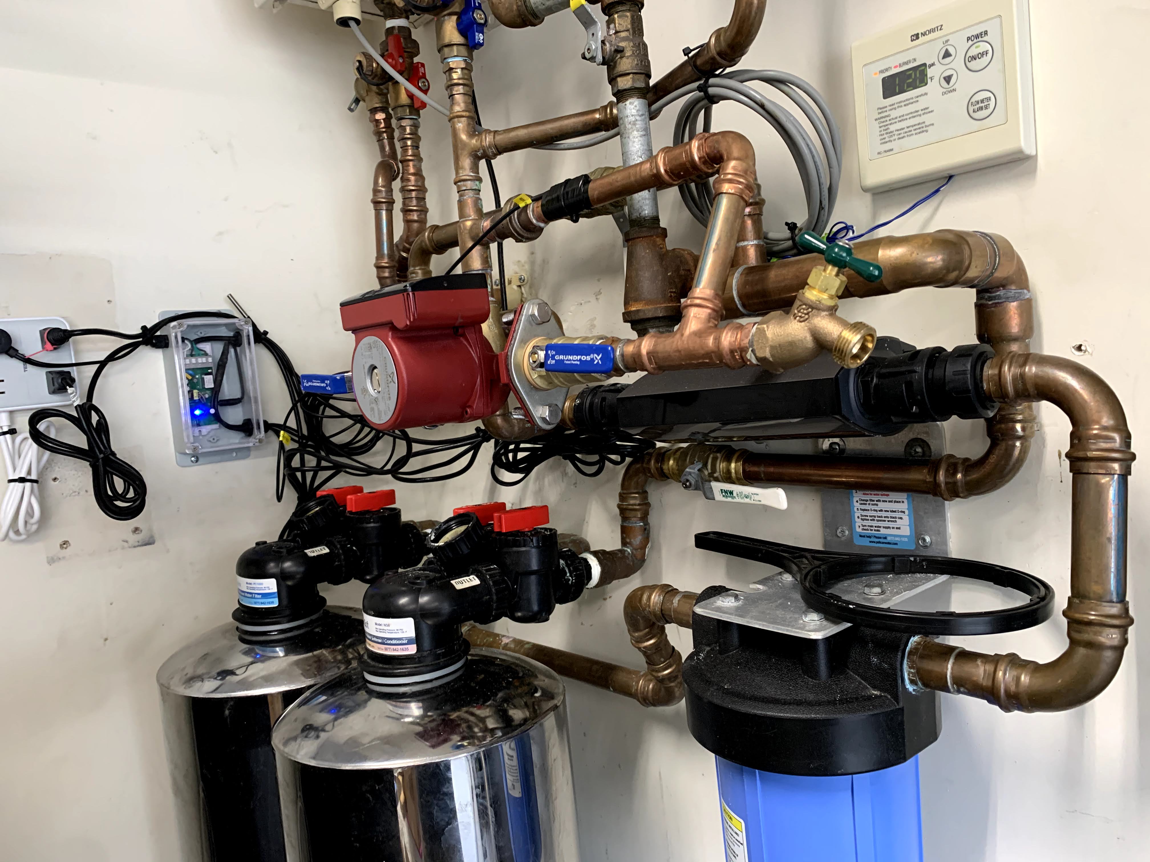
Our house uses a Noritz natural gas instant hot water heater, with a dedicated hot water recirculation line. Problem is the heater is installed in the garage, and in the summer the the garage gets so hot that the aquastat that controls the recirculation pump never turns on. This leaves us with cold water in the recirculation line, and we have to wait several minutes for hot water, defeating the entire purpose of the instant hot recirculation line.
Our Grundfos recirculation pump uses a 85F (29.4C) to 105F (40.6C) thermostatic control. The circulation pump will turn on when the temperature drops below 85F, the water flow turns the heater on, and the pump will keep running until the temperature exceeds 105F. The garage temperature in the summer often exceeds 85F, which keeps the aquastat satisfied, and the pump never runs.
One option is to periodically circulate the water in the line allowing the aquastat to measure the temperature of the water in the line, not just the stagnant water in the garage, that reaches thermal equilibrium with the garage ambient temperature.
I chose a Sonoff TH10 WiFi relay controller, based on ESP8285/8266, running ESPHome on the controller, and monitored using Home Assistant. I could have used a TH16, but the 10A relay in the TH10 is sufficient to power the circulation pump, and it makes for a smaller unit.
The code is on GitHub, where I used a Bang Bang controller as thermostat, and an interval timer to periodically run the pump. The code is reasonably simple, with the timer section taking care to only modify the relay state if the thermostat is not already calling for heat.
Assembly and installation instructions:
- Warning : I accept no liability, only proceed if you are qualified to work with residential high voltage.
- Warning : Do not connect the TH10 to AC power while assembling or programming!
- Warning : Do not connect or remove the TRRS plug while the TH10 is powered on!
- Remove the TH10 from its protective cover, just pry the cover open and it will snap open.
- Remove the screws holding the PCB down, solder pin headers to the PCB, and re-attach the PCB to the case.
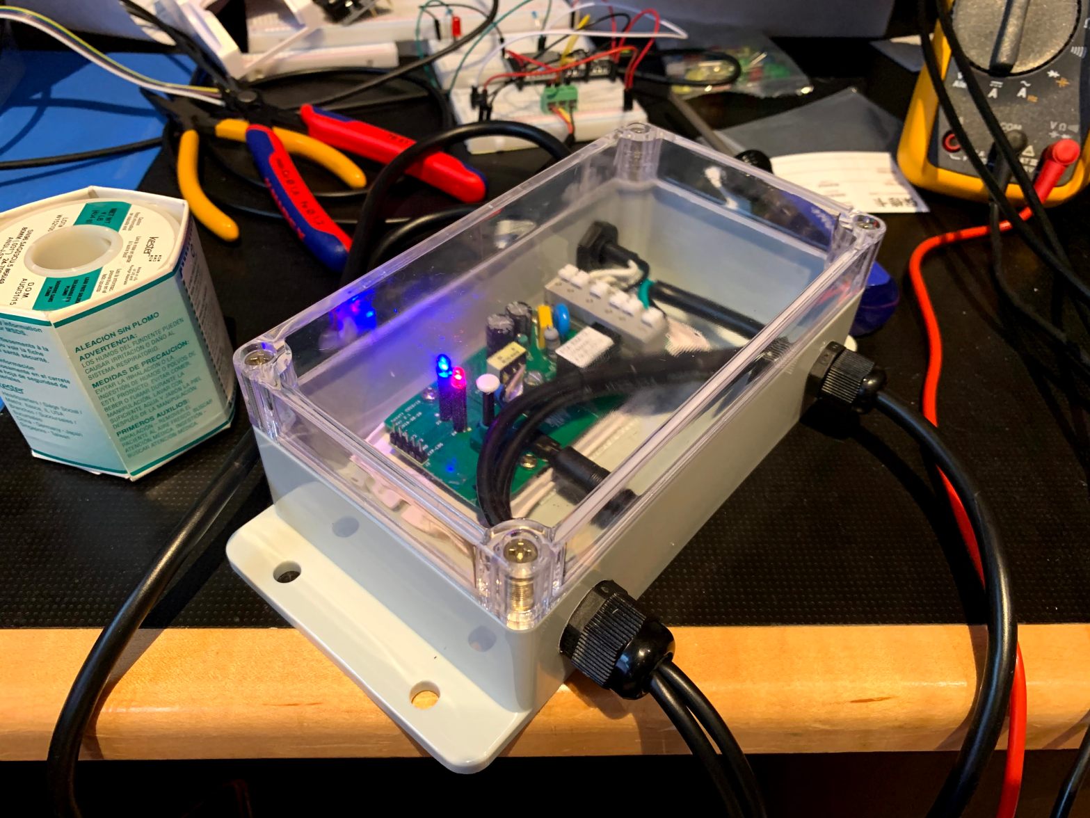
- I used a splashproof plastic case with a transparent lid to house the TH10 and wires.
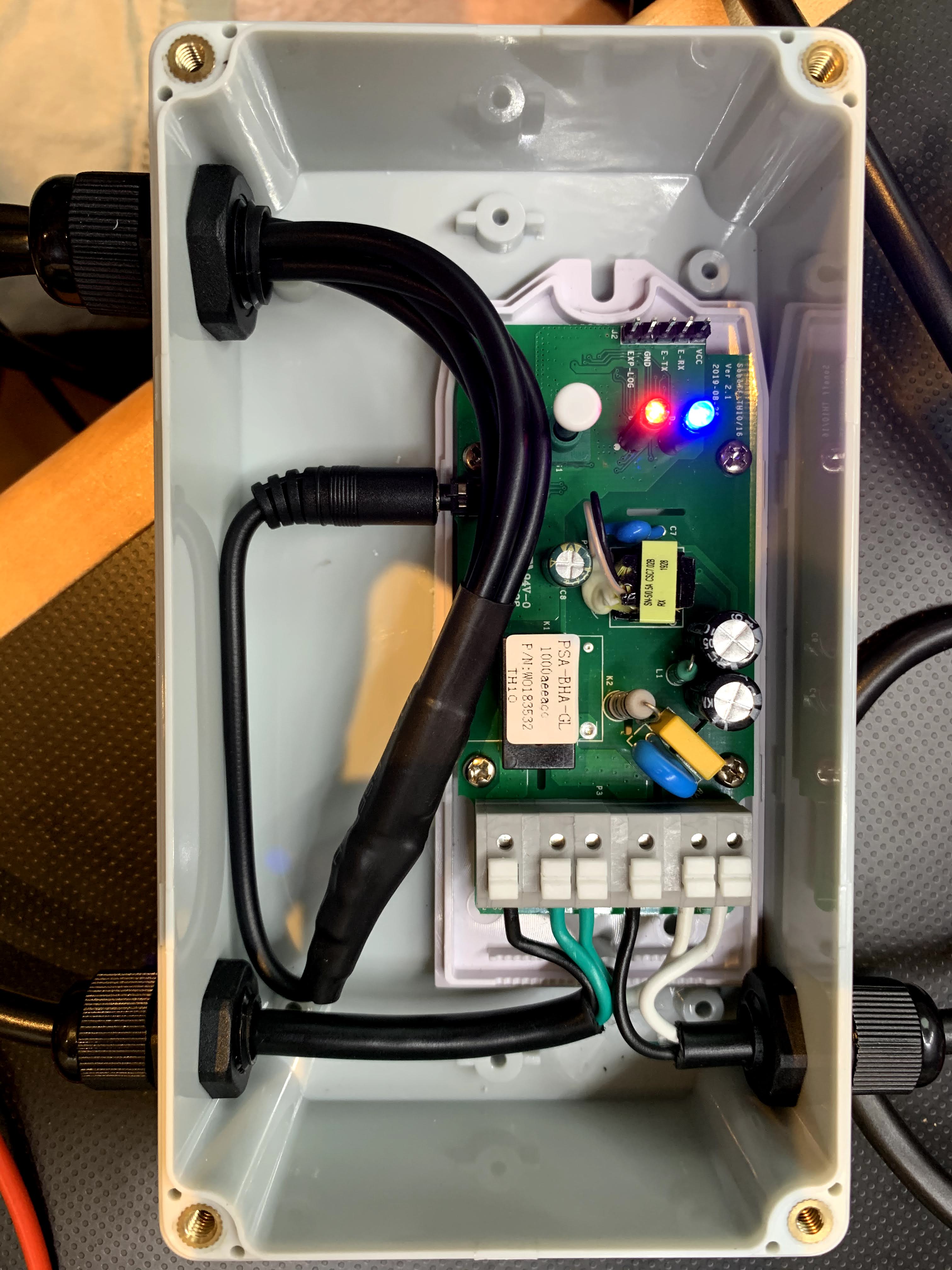
- Drill a hole in the case and mount a 9mm cable gland used for the four temperature sensor cables, I ran all four cables through one gland.
- Drill two holes in the case and mount 7mm cable glands for the power -in and -out cables.
- Solder four Dallas 18B20 waterproof temperature probes to the the 2.5mm TRRS connector, and insulate and protect using heat shrink tubing. Verify your specific TRRS cable wiring colors.
- GPIO14 : TRRS Tip : TRRS Red : Dallas Yellow
- GND : TRRS Ring 2 : TRRS Green : Dallas Black
- 3.3V : TRRS Shield : TRRS Black : Dallas Red
- Run the TRRS connector with four temperature probes attached through the gland into the case, secure the gland, and plug the TRRS plug into the TH10.
- Attach the TH10, without its top cover, to the inside of the case using removable velcro tape strips.
- Set your FTDI programmer to 3.3V and connect the relevant pins to the TH10, hold the TH10 button down during power-on to enter programming mode.
- Compile and download the project firmware in ESPHome, and program the TH10 using ESPHome Flasher. Wired programming is only required once to replace the Sonoff factory firmware with ESPHome, after which ESPHome OTA updates can be applied.
- While still using the the FTDI programmer for power, verify the TH10 connects over WiFi and is operational in ESPHome and Home Assistant.
- Look at the debug output to discover your specific Dallas sensor addresses, make appropriate corrections to the sensors section in the ESPHome YAML file, and reprogram OTA.
- Use Home Assistant to monitor the four probe temperatures as you warm each up by hand, and mark the probes with associated names using a label maker.
- I used two NEMA 5-15P to NEMA 5-15R cables, cutting them to length as needed, stripping and tinning the exposed ends.
- Run the NEMA 5-15P plug through the gland into the case, secure the gland, and connect to the TH10 power input.
- Run the NEMA 5-15R plug through the gland into the case, secure the gland, and connect to the TH10 power output.
- Close and seal the case lid, mount on the wall near the circulation pump and a power outlet.
- Remove the aquastat from the circulation pump, the pump should only be powered and controlled by TH10.
- Attach the ambient temperature probe to the outside of the case.
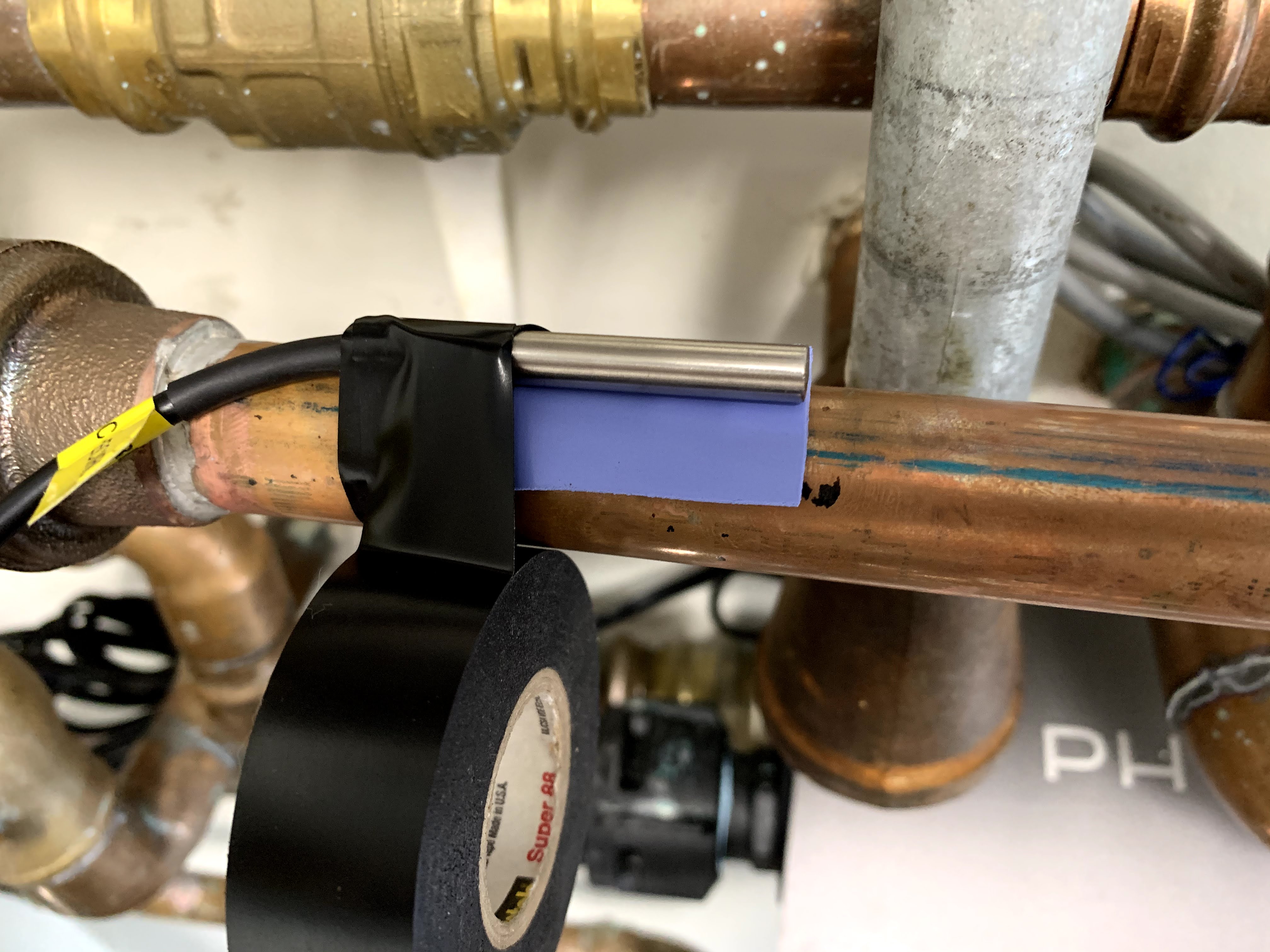
- Attach the recirculation-, hot-, and cold- temperature probes to the associated plumbing lines. Attach a thermal conductive pad between the sensor and copper plumbing, wrap using heat resistant insulation tape, and secure the sensor to the plumbing with a cable tie.
- Connect the TH10 NEMA 5-15P plug to AC power, verify TH10 connects over WiFi and is operational in ESPHome and Home Assistant.
- Connect the circulation pump to TH10 NEMA 5-15R plug.
- Monitor the pump behavior and line temperatures, adjust the temperature and timer values as needed.
Assembly and installation pictures:


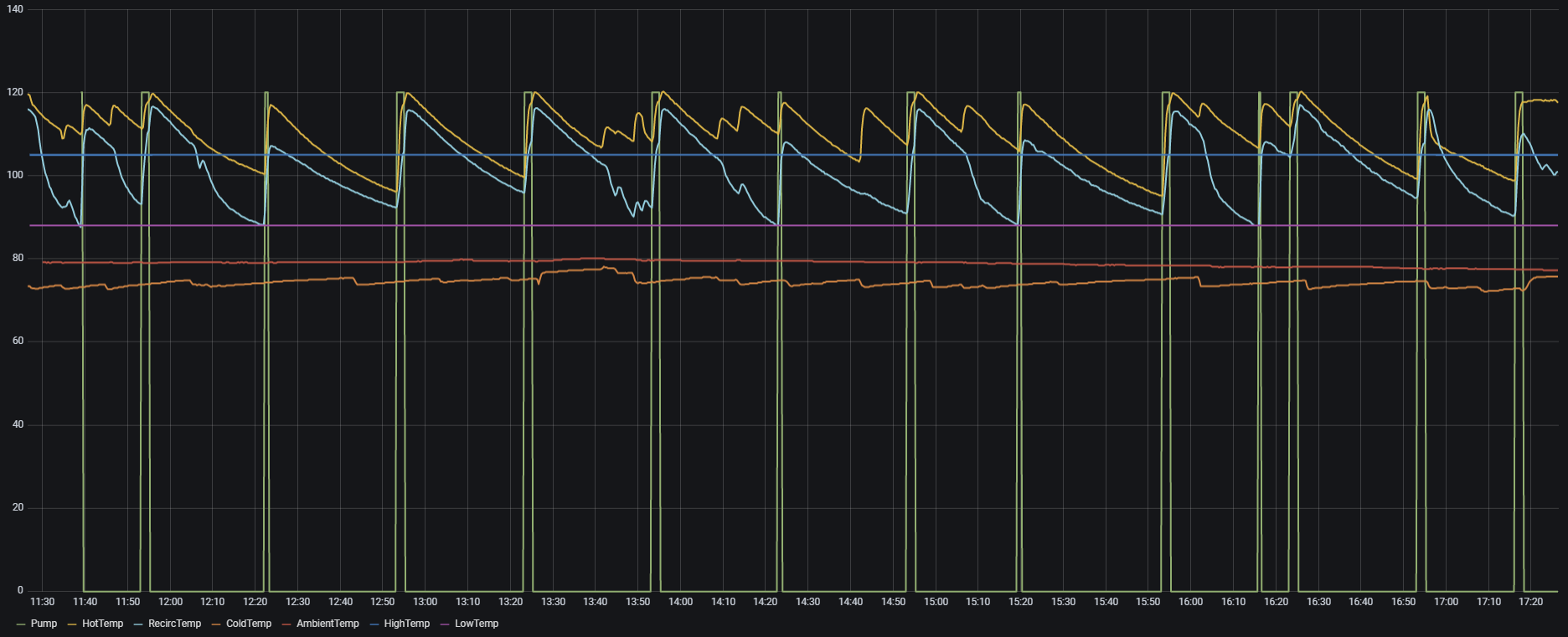
Below is a graph showing the temperatures and pump activity over a 6 hour period. It would be interesting to compare the summer pattern with a winter pattern, where I expect the thermostat to trigger more than the timer.
I am noticing some instability, with the controller randomly restarting due to a Reset Info: Fatal exception:4 flag:1 (Hardware Watchdog) error. Fortunately nothing bad happens, the timer just resets, but I will keep investigating. Remote debugging will require serial connectivity, which is a bit tricky, but I may try to install a ESP-01 running esp-link in the same case as the TH10, and use that for remote diagnostics.
I would still like to figure out a way to monitor the gas heater activity, maybe optically monitoring the LED state? And I do wish I could monitor the water flow rate from the Phyn, but unfortunately no user access to data.

1 Comment
Comments are closed.